Page 6
Building the circuit
The first thing to do is to connect the hardware components, creating a circuit. An electronic circuit is a complete course of conductors (objects that allow the flow of electrical current) through which current can travel, forming a loop. Circuits provide a path for current to flow.
Connecting the components
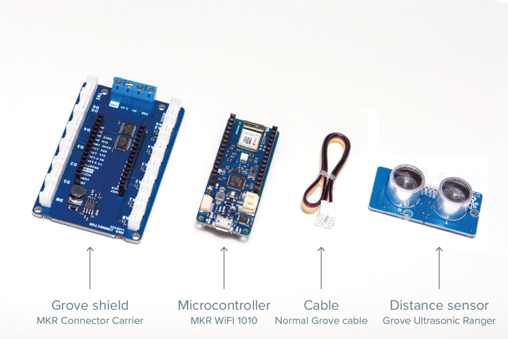
The three components presented in the previous pages need to be connected:
- the microcontroller (MKR WiFi 1010)
- the distance sensor (Grove Ultrasonic Ranger)
- the Grove base shield (MKR Connector Carrier)
A standard Grove cable is required to connect the sensor to the shield. You will find a Grove cable in the box of components.
Step 1: Connect the microcontroller to the Grove shield, checking that the labelled pins match.
Step 2: plug the cable into the Grove shield, using the first digital input/output (I/O) pin, labelled as D0. Grove connectors can only go in one way. Check that it is going the correct way before applying too much force.
Step 3: plug the other end of the cable into the distance sensor.
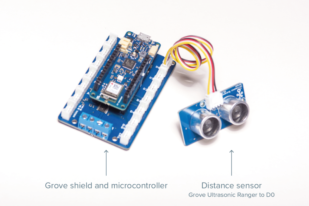
The Grove Ultrasonic Ranger sensor is directional: aiming the front of the sensor to an object will measure the distance between that object and the sensor.
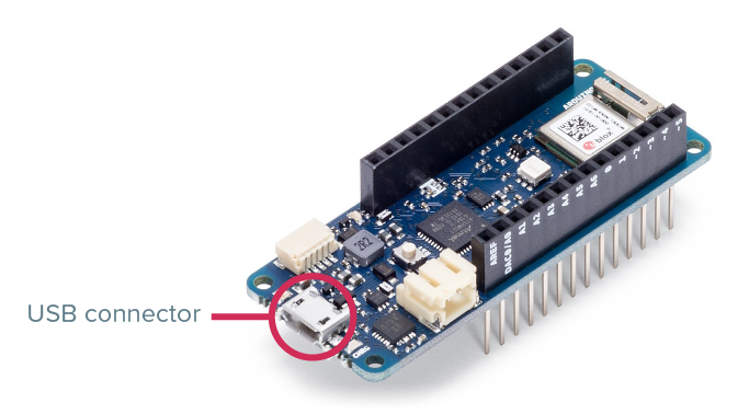
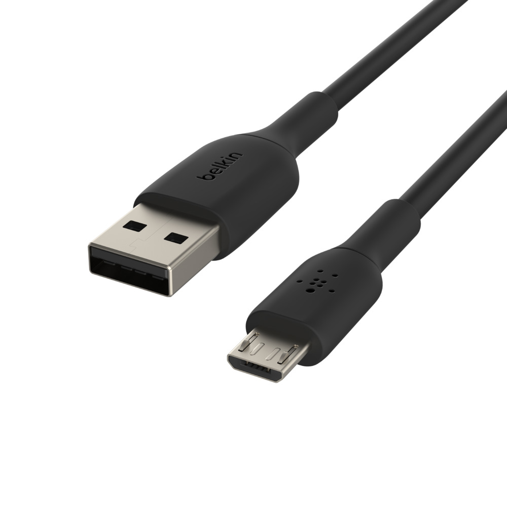
To connect the circuit to your computer, you need to use a MicroUSB cable. The micro connector will plug into the Arduino board, and the standard USB connector will plug into a USB port in your computer.
Give yourself a pause.
Congratulations! You have completed the hardware part of this tutorial. You have created an electronic circuit that will capture physical measurements in the environment (in this case, distance). Before moving into the software part of the tutorial, take a moment to celebrate this achievement!
Continue to Page 7 – Software.