Checkbox 2
The board can run a custom program
The next step will be to test the microcontroller with a custom program.
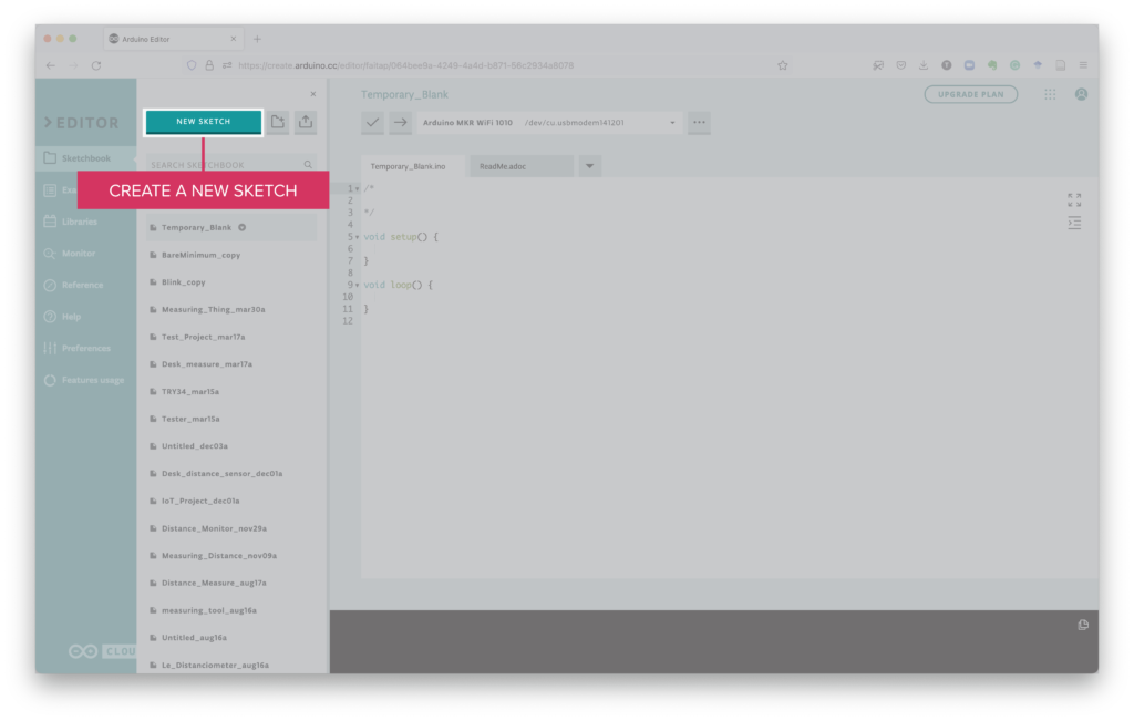
Start by going to the Arduino IoT Cloud Web Editor and creating a new sketch.

The blank sketch will present this code, that is just an empty skeleton:
/*

*/

void setup() {

}

void loop() {

}
We will guide you to create a custom piece of code that will test and change the digital input/output ports on the microcontroller.
Setup function
Identify the beginning of the setup function:
void setup() {After that, add the following lines:
  Serial.begin(9600); // open a communication port
  for (int a=0; a<8; a++) { // loop through the ports
    pinMode(a, OUTPUT); // set the port as OUTPUT
  }
The first line, opens a communication port between the microcontroller and the computer.
The following lines, defines ports 1-8 as outputs.
Check that the setup function closes correctly with a curly bracket:
}Loop function
Identify the beginning of the loop function:
void loop() {After that line, add the following code:
  Serial.println("Turning the ports on");
  writeDigital(HIGH);
  readDigital();
  delay(5000); // wait 5 seconds

  Serial.println("Turning the ports off");
  writeDigital(LOW);
  readDigital();
  delay(5000); // wait 5 seconds
Verify that the loop function closes with the corresponding curly bracket:
}The code you have written above calls two new functions that we need to create:
- one to change the state of the digital ports – writeDigital
- one to read the state of the digital ports – readDigital
At the bottom of the page, outside the curly brackets enclosing the loop function, add the following code:
/* Custom functions */
void writeDigital(uint8_t value) {
  for (int a=0; a<8; a++) { // loop through the ports
    digitalWrite(a, value);
  }
}

void readDigital() {
  for (int a=0; a<8; a++) { // loop through the ports
    Serial.println("Port " + String(a) + " -- Status: " + String(digitalRead(a)));
  }
}
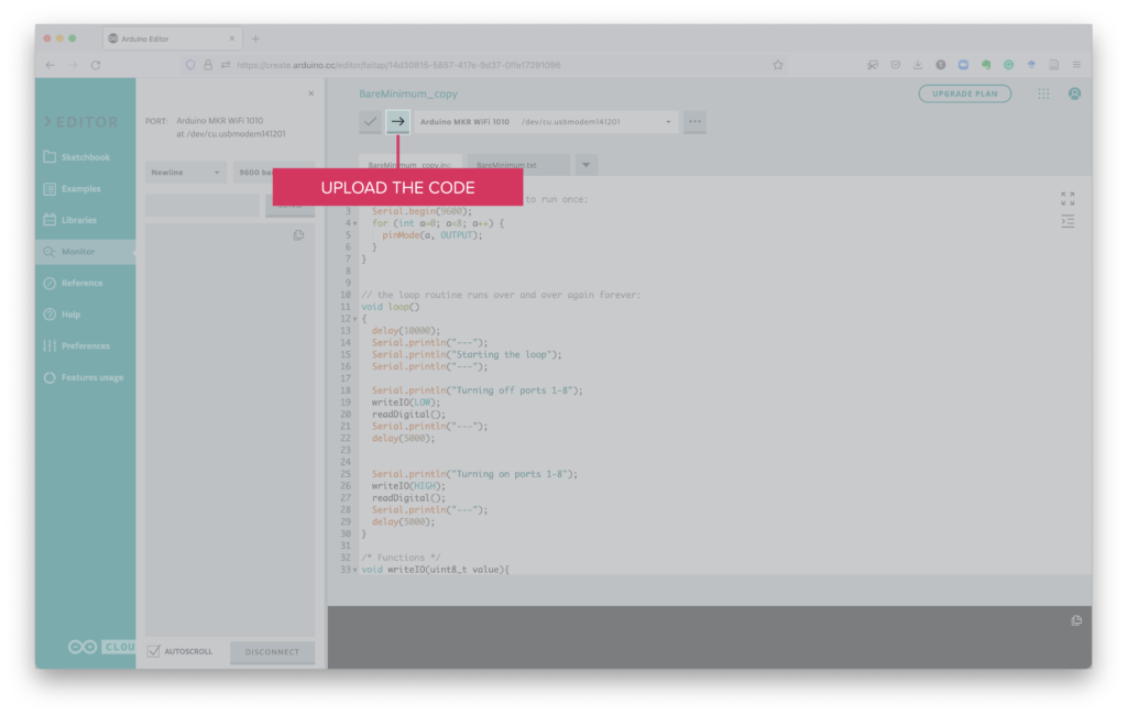
Once the code finish uploading to the board, you should see a success message at the bottom of the screen:
Success. Saved on your online Sketchbook and done uploading […]

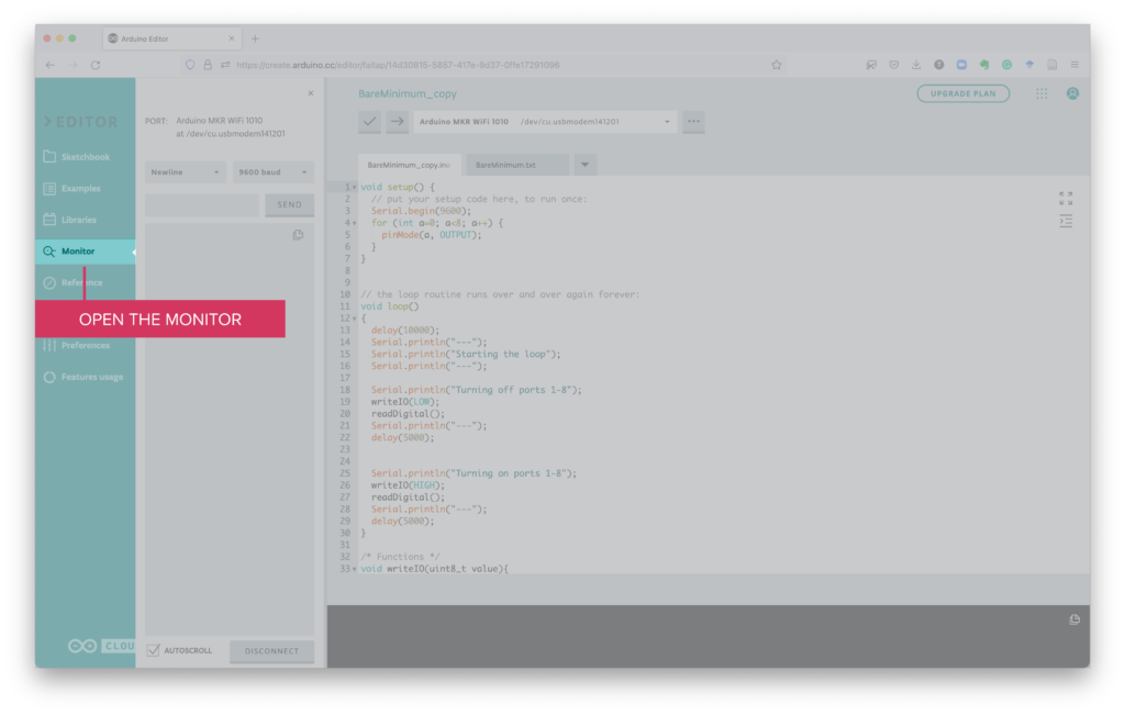
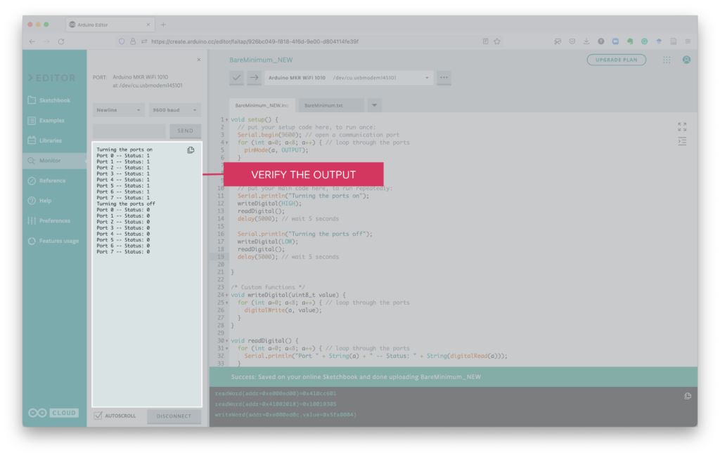
If all went well, you should see messages indicating that the ports are turned on (Status: 1), and subsequently turned off (Status: 0).